Different Types Of Relays, Their Construction, Operation & Applications
Introduction To Relay & Different Types Of Relays | Its Terminals, Working & Applications
Relays are the essential component for protection & switching of a number of the control circuits & other electrical components. All the Relays react to voltage or current with the end goal that they open or close the contacts or circuits. This article briefly discusses the relay basics & different types of relays that are utilized for a variety of applications.
What is a Relay?
A switch is a component that opens (turn off) & close (turn on) an electrical circuit. whereas, a relay is an electrical switch that control (switch on & off) a high voltage circuit using a low voltage source. A relay completely isolates the low voltage circuit from the high voltage circuit.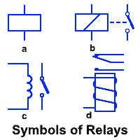
Construction of a Relay
To know the basic construction and internal parts of a relay, the following fig clearly shows an inside view of a relay. Lets discuss all of them one by one.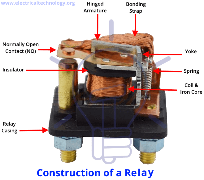
Terminals Of Relay
Generally speaking, there are four types of terminals in a relay.
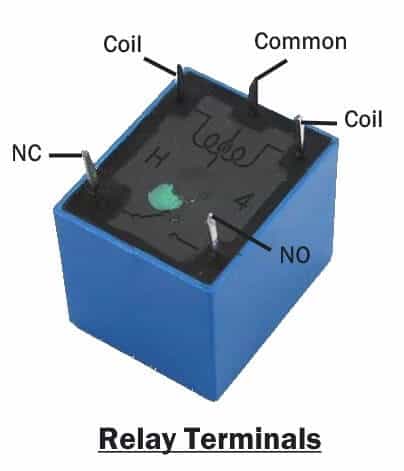
Control Input or Coil Terminals:
Control input terminals are two input terminals of a relay that controls its switching mechanism.
A low power source is connected to these terminals to activate & deactivate the relay. The source can be AC or DC depending on the type of the relay.
- COM or Common Terminal:
COM refers to the common terminal of the relay.
This is the output terminal of the relay where one end of the load circuit is connected.
This terminal is internally connected with either of the other two terminals depending on the state of the relay.
NO Terminal:
NO or Normally Open terminal is also a load terminal of a relay which remains open when the relay is not active.
The NO terminal becomes closed with the COM terminal when the relay activates.
NC Terminal:
NC or Normally Closed terminal is the other load terminal of a relay. This terminal is normally connected with COM terminal of the relay when there is no control input.
When relay activates, the NC terminal disconnects from the COM terminal & stays open until the relay is deactivated.
Poles & Throw:
Poles refer to the switches inside a relay.
The numbers of Switches inside a relay is called the poles of the relay.
The number of circuits being controlled per pole is called the throw of a relay.
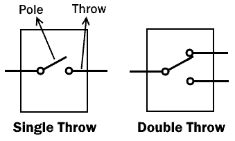
A single throw relay can control only one circuit i.e. either OFF or ON, while a double throw relay can control two circuits i.e. alternating from one circuit to another by opening one circuit and closing another during switching (ON & OFF).
Relay Operation:
Assume an SPDT (single pole double throw) relay
When there is no power source, the relay is inactive & the position of its pole remains at NC terminal, which in the above-mentioned case happens to be the upper terminal. This results in an electrically short path between the COM terminal & NC terminal. Thus it allows the flow of current through the circuit connected to COM & NC terminal.
When the relay is powered on using a low voltage source, the pole of the relay shifts to the NO terminal. Thus the NC terminal becomes open & the COM terminal becomes closed or electrically short to NO terminal. Subsequently, allowing the flow of current through the circuit connected with COM & NO terminal.
Types Of Relay:
There are various types of relays & they are classified into different categories according to their properties. Each of these types of relays is used for a specific application & it is necessary to select the appropriate relay before using in any circuit.
Based on Poles & Throw:
These following types of relays are classified by the numbers of poles & throw inside a relay.
SPST Relay
SPST refers to single pole single throw relay.
The single pole means that it can control only one circuit while the single throw means its pole has only one position in which it can conduct. SPST diagram is given below.

The SPST relay two states I.e. either Open or Close circuit.
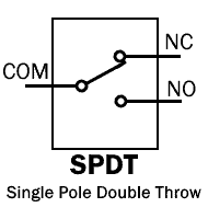
SPDT Relay
SPDT refers to single pole double throw relay.
The single pole means it can control only one circuit at a time. The double throw means its pole has two positions in which it can conduct.
The SPDT relay has two states & in each state, its one circuit remains closed while the other remains open & vice versa.
DPST Relay
DPST refers to double pole single throw.
The double pole means it can control two completely isolated individual circuits. The single throw means that each pole has one position in which it can conduct.
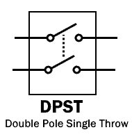
The DPST relay can switch two circuits simultaneously i.e. either providing a close or open circuit.
DPDT Relay
DPDT refers to double pole double throw.
The double pole means it can control two circuits while the double throw means each pole can conduct in two separate positions.

The DPDT relay can be interpreted as two SPDT relays but their switching is simultaneous.
A relay can have as many as 12 poles.
- Forms Of Relay
Types of relays are also classified based on its configuration known as “Forms”.
“Form A” Relay
“Form A” is an SPST relay with normally open (NO) default state.
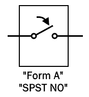
It has NO terminal that connects the circuit when the relay is activated & disconnects the circuit when the relay deactivates.
“Form B” Relay
Form B relay is SPST relay with normally closed (NC) default state.
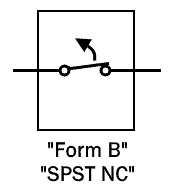
The NC terminal connects the circuit while the relay is inactive & it disconnects the circuit when the relay activates.
“Form C” Relay
Form C relay is SPDT relay with double throw contact terminals known as NC & NO.

It controls two circuit i.e. one circuit remain open while the other remains closed. It is also known as “break-before-make” relay because it breaks open one circuit before closing the other circuit.
“Form D” Relay
Form D relay is also an SPDT relay and has the same principle as Form C relay but it is “make-before-break” contact relay.

It closes the next circuit before breaking (opening) the first circuit. It is used for not disrupting the continuity of the circuit.
Based On Operation Principles:
These following types of relays are classified based on their different operation principles.
EMR (Electromechanical Relay)
This type of relay has an electromagnetic coil and a mechanical movable contact.
When the coil is energized it produces a magnetic field. This magnetic field attracts the armature (movable contact). When the coil is de-energized the coil loose magnetic field and a spring retract the armature to its normal position.

The EMR relay is designed for AC or DC source depending on the application it is used for. The structure of AC & DC EMR relay differs from each other by having a slight difference in its coil construction. The DC coil has a freewheeling diode for protection against back EMF & de-energizing the coil.
The polarity of the source in EMR relay does not matter, it energizes the coil in either way but if there is a back EMF diode installed then polarity should be considered.
The main disadvantage of EMR relay is that its contacts produce arc during breaking which leads to increasing its resistance over time & decreasing the lifespan of the relay.
- Related post: Types of Latches – SR & D Latches
SSR (Solid State Relay)
SSR relay is made up of semiconductors instead of mechanical parts and it works on isolating the low voltage circuit from high voltage circuit using an optocoupler.
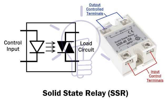
When the control input is applied to a solid state relay, an LED lights up which produce infrared light. This light is received by a photosensitive semiconductor device which converts the light signal into an electrical signal and switches the circuit.
SSR operates on relatively high speed & has very low power consumption as compared to EMR relay. It has a longer lifespan because there are no physical contacts to burn out.
The main disadvantage of SSR relay is its nominal voltage drop across the semiconductor which wastes power in the form of heat.
Hybrid Relay:
Hybrid relays are made using both SSR & EMR relays.
As we know that the SSR wastes power in form of heat and EMR has contact arcing problem. The hybrid relay uses both SSR & EMR to overcome their disadvantages.

In Hybrid relay, SSR & EMR are used in parallel. A relay control circuit is used for switching the SSR first. The SSR takes the load current. So it eliminates the arching problem. Then the control circuit energizes the EMR coil & its contact closes but there is no arching since the SSR is taking the load in parallel. After some time, when the EMR contact settles down, the control input of SSR is removed. The EMR conducts the entire load current without any loss. Since there is no current flow throw SSR & the EMR takes the entire load, there is no power loss in form of heat. Thus, it eliminates the heat problem too.
Reed Relay
Reed relay is made up of a reed switch & an electromagnetic coil with a diode for back EMF.
A reed switch is made up of two metal blades made up of ferromagnetic material hermetically sealed in a glass tube which also supports the metal blades. The glass is filled with inert gas.

When the coil is energized, the ferromagnetic metal blades attract each other and form a closed path. As there is no moving armature so there is no contact wear-out problem. The glass tube is also filled with inert gas which also prolongs its life.
Electrothermal Relay (Thermal Relay):
An electrothermal relay is made up of bimetallic (made up of two metals having different thermal expansion coefficients) strip.

When the current flow through the conductor, it produces heat. Due to which the temperature of the bimetallic strip rises and expands. The metal having high thermal expansion coefficient expands more than the other metal. Due which the strip bends & closes the contacts to usually activate the trip circuitry.
Thermal relays are usually used for electric motor protection.
Polarized & Non-polarized Relay
The polarized relay uses a permanent magnet with an electromagnet. The permanent magnet provides a fixed position for the armature. The electromagnetic coil changes the position of the armature about a fixed pivot. The armature position depends on the polarity of the control input.
The non-polarized relay does not use permanent magnets & their coil can be energized in both ways without affecting its operation. Some relay having back EMF diodes does have polarity since the diode will bypass the coil if the connection is reversed.
Application Of Relay
- Relays are used for isolating a low voltage circuit from high voltage circuit.
- They are used for controlling multiple circuits.
- They are also used as automatic change over.
- Microprocessors use relays to control a heavy electrical load.
- Overload relays are used for protection of motor from overload & electrical failure.
These are some of other types of relays used in various electrical & electronic circuits. This article provides the necessary knowledge about “the relay & types of relays” to understand their basic principles & differences.

Certificate No.CERT001561786-EMI

🥇BE-Electrical🥈 PGDM-Marketing. 🥉Data Scientists. 🏅MEP-Electrical.

This Page is a little effort to make you Sharing of some own materials .This is just a Kick-Start to make the aware of Practical World !!! Best of luck.-DHRUVANG SUTHAR
0 Comments